
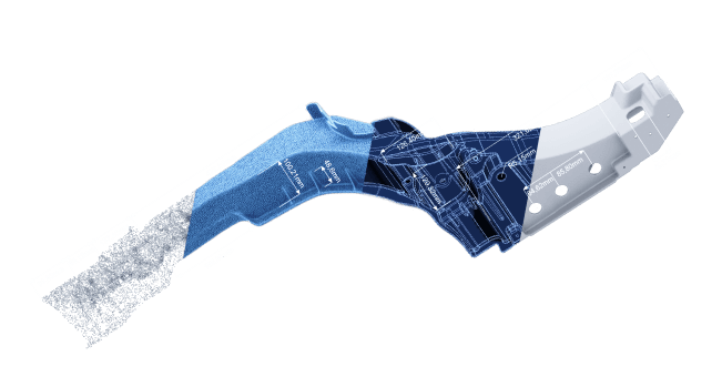


A striped pattern is projected onto the object. Stereo cameras determine the surface geometry from the reflection.
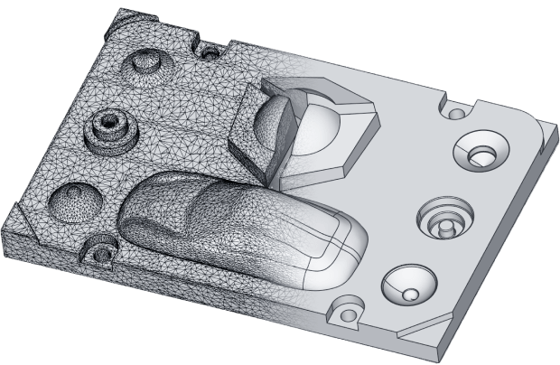
Converting a 3D scan as accurately as possible into a CAD solid model. This technique is for objects with simple geometries.
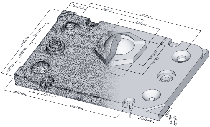
This technique allows us to convert a 3D scan into the native CAD format or whatever CAD software our client is using.
Either we 3D scan your part or you provide us with a 3D Scan
We complete the Reverse Engineering (STL to STEP)
We provide you the download link to your files
With reverse engineering we can convert a 3D scan into a CAD format. STL to STEP conversion is an example of reverse engineering.
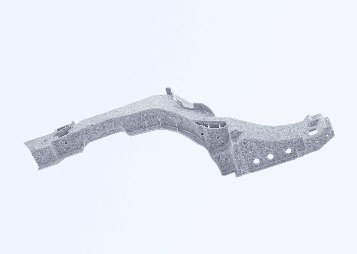
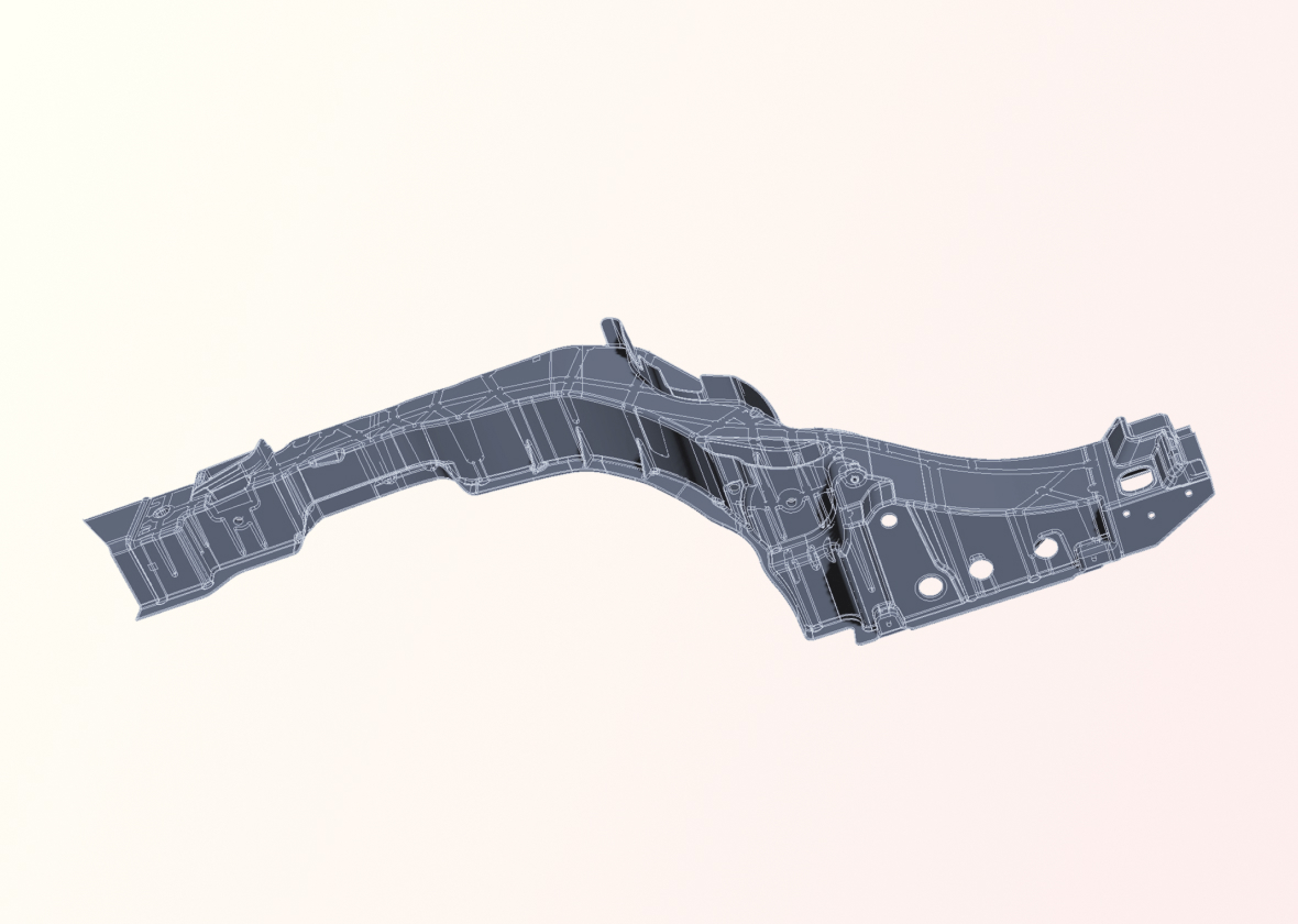
Either you can provide us with 3D data to reverse engineer or you can provide us with a mechanical part to 3D scan ourselves. Once we have a 3D scan to work with, we can use special software to reverse engineer the part. Finally, we provide you with the CAD data to download so that you have all the information you need.
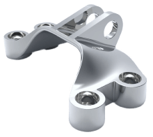
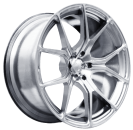
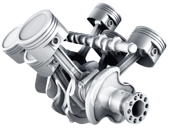

Depending on the selected reverse engineering procedure, we can provide your data in the neutral CAD exchange formats STEP, IGES, X_T, or in the native CAD format of the specific CAD software you personally use.
With the reverse engineering to surface model, we can convert a 3D scan into a CAD surface model.
This technique for reverse engineering is particularly suitable for organically shaped parts with curved surfaces. The aim is to keep the deviations between your 3D scan and your surface model as small as possible. Manufacturing defects of the original 3D-scanned part are transferred to the reverse engineered surface model, because an error correction would be at the expense of the reconstruction accuracy.
Reverse engineering to solid model allows the conversion of a 3D scan (STL) into a CAD solid model (STEP). The goal is to keep the deviations between the 3D scan and solid model as small as possible. There is no correction of manufacturing defects of the 3D scanned part so that accuracy can be maintained. The resulting solid model can consist of simple geometries or complex NURBs surfaces. When simple geometry and NURBS are combined in one model, it’s sometimes called a “hybrid”.
Reverse engineering to parametric modeling with a history tree involves converting a 3D scan into your native CAD format. The finished CAD model thus contains a history tree, and you can adjust all parameters yourself in your own CAD program. A technical drawing can be derived from the parametric CAD model with little effort.
We make videos about 3D-scanning and reverse engineering. We will happily inform you when a new video goes online.

