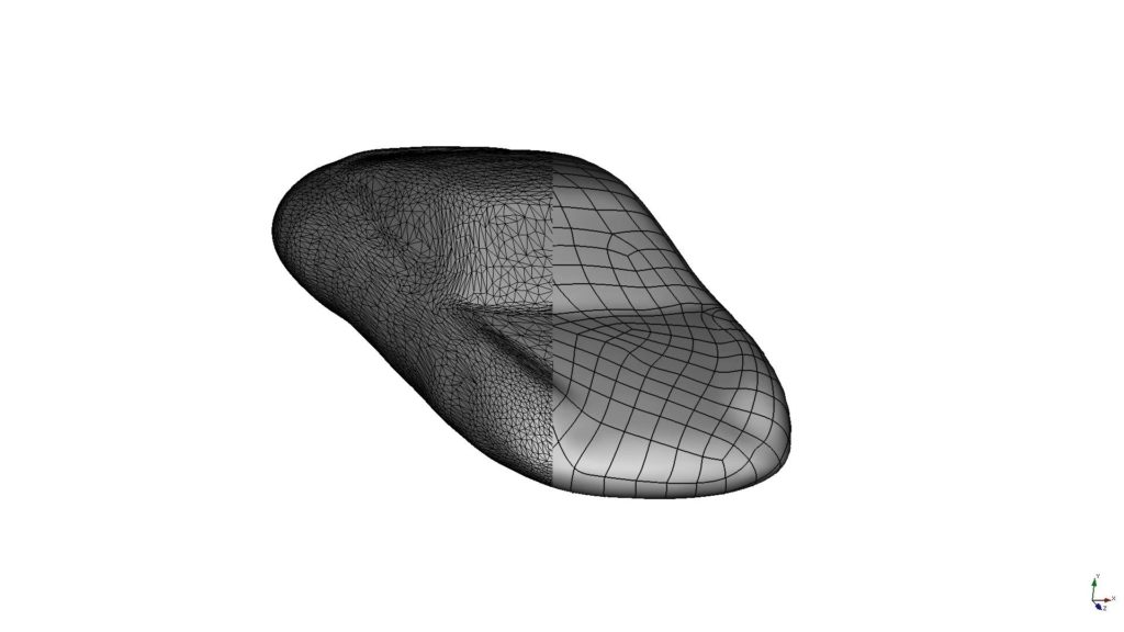
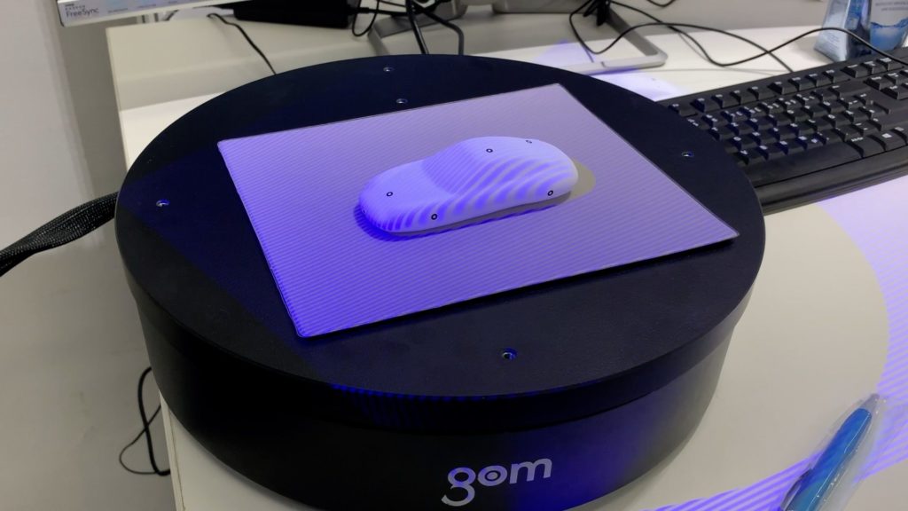
As a starting point for reverse engineering, the 3D data should be available as a polygon mesh (STL) or in a point cloud format. Alternatively, we at Holocreators can create a 3D scan for you. For this purpose, you can either send us your part by mail or we can 3D scan directly at your site.
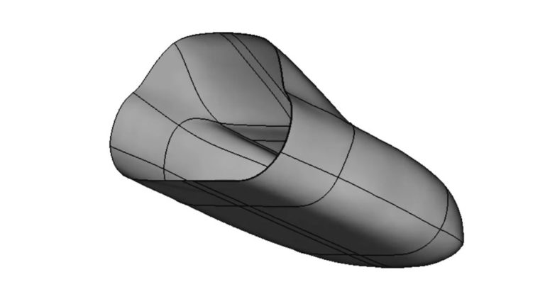
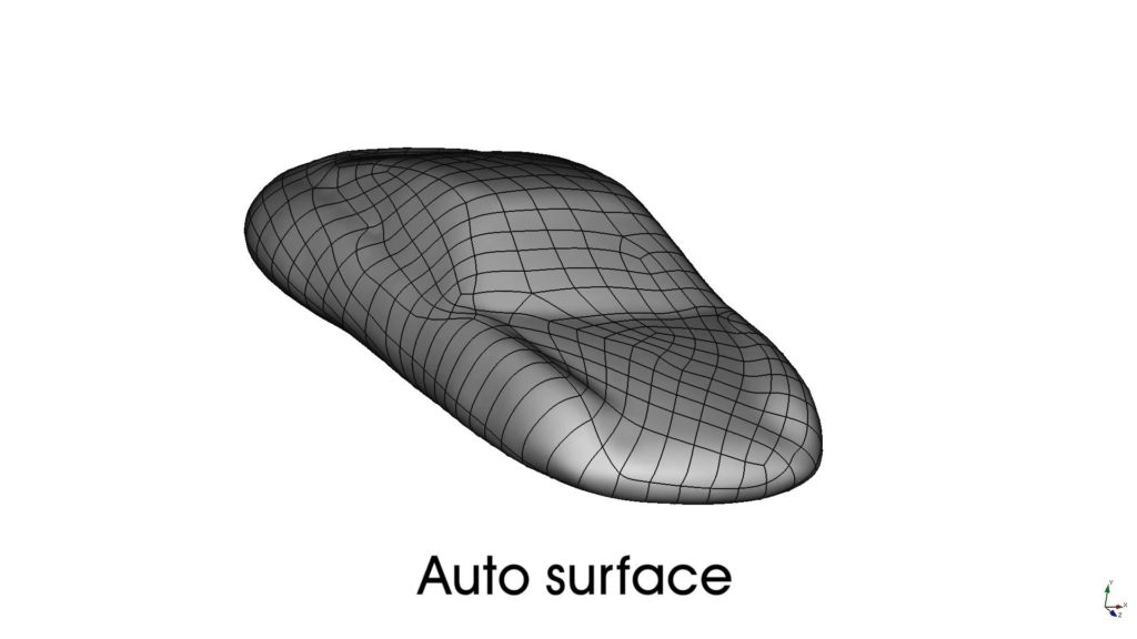
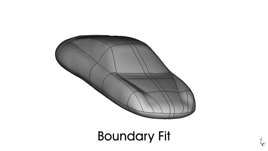
With the help of reverse engineering to surface model, the existing 3D scan is converted into a CAD format. For this purpose, the NURBs surfaces are molded from the underlying 3D Scan. There are two different variants: Either the reverse engineering is done fully automatically (Auto Surface) or the NURBs curves are defined manually and the surfaces in-between are generated automatically (Boundary Fit). Which variant is used is determined by the part’s geometry and your intended use.
Both variants result in a NURBs surface model that cannot be edited later.
After the successful reverse engineering to surface model, the 3D data is output as a CAD surface model. Only under certain conditions can the surface model be closed and converted into a solid model.
The CAD model can be exported in the neutral CAD exchange formats STEP, IGES and X_T.
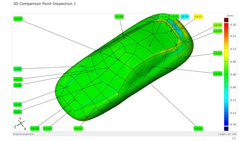
Reverse engineering with surface modeling is very accurate. On average, the generated surface model deviates only up to 0.05mm from the original 3D scan.
This high accuracy is achieved by the automatic molding of the NURBs surfaces from the underlying 3D scan. However, to achieve this high accuracy, manufacturing defects of the 3D scanned part are also transferred to the resulting CAD surface model.
Yes. After reverse engineering, we create a deviation analysis which compares the original 3D scan with the generated surface model. Any deviations are shown with a color scheme and markers that display how far the reverse engineering deviates from the underlying 3D scan.
